
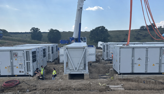
Drawing on nearly two decades of power electronics development and more than 5,000 energy storage projects, Sinexcel technical director Luke Lu discusses what goes into a successful grid-forming battery energy storage system (BESS) project.
Grid-forming capability is increasingly appearing in grid codes, connection requirements and specifications for utility-scale battery energy storage systems (BESS). But specifying grid-forming functionality is only the beginning.
For developers and EPCs, the harder question is: how can grid-forming capability be translated into a BESS that is compliant, stable and ready for successful commissioning under real grid conditions?
A power conversion system (PCS) may support grid-forming control on its datasheet, but a real project still has to pass grid studies, interact correctly with the battery and plant controller, operate within physical current and thermal limits, and ultimately demonstrate the expected behaviour onsite.
Try Premium for just $1
- Full premium access for the first month at only $1
- Converts to an annual rate after 30 days unless cancelled
- Cancel anytime during the trial period
Premium Benefits
- Expert industry analysis and interviews
- Digital access to PV Tech Power journal
- Exclusive event discounts
Or get the full Premium subscription right away
Or continue reading this article for free
This is where grid-forming (GFM) moves from being a product feature to a project-engineering challenge. Five areas deserve particular attention.
1. Start with the grid code, not the PCS datasheet
One of the most common risks in early project development is selecting equipment first and interpreting the grid-connection requirements later. The sequence should be reversed.
Before finalising the PCS configuration, developers and EPCs should translate local connection requirements into clearly defined technical behaviours, including:
- active and reactive power capability;
- voltage and frequency response;
- LVRT and HVRT;
- reactive current injection;
- ramp rates;
- fault behaviour;
- protection settings;
- modelling and validation requirements
- increasingly, specific grid-forming functions.
This matters because connection requirements vary not only between countries but also between network operators, voltage levels and, in some cases, individual connection points. Grid-code compliance should therefore not be treated simply as a certification exercise.
The requirements can influence converter controls, plant-level settings, protection philosophy, modelling strategy and even aspects of the overall system architecture.
For example, SINEXCEL’s utility-scale PCS supports multiple operating modes, including PQ, VF and VSG control, as well as black start and configurations adapted to different grid requirements. But which functions are required, and how they need to be configured and validated, ultimately depends on the project.
Discovering these requirements too late can lead to model revisions, control changes, additional testing and, in the worst case, delays to energisation and commercial operation. The earlier grid requirements are translated into engineering requirements, the lower the risk of redesign during the connection and commissioning process.
2. Break ‘grid-forming’ into behaviours that can actually be tested
Grid-forming is frequently discussed as if it were a single feature. It is not. From an engineering perspective, it is better understood as a collection of behaviours that need to be specified, modelled and validated individually.
Black start
Can the BESS establish voltage and frequency without relying on an external grid reference, and can it energise the intended network under the required conditions?
Virtual synchronous generator control
Can the converter provide the required virtual inertia and damping characteristics, and how does it respond during frequency disturbances?
Weak-grid operation
How does the system behave as short-circuit strength decreases? Does the control remain stable under the actual grid conditions expected at the point of connection?
Fault ride-through
Can the PCS remain connected and provide the required active and reactive current response during voltage disturbances while respecting its physical current limits?
Transient current and overload capability
How does the system respond to transformer energisation, motor starting, sudden load steps or other short-duration demands?
Islanding and operating-mode transitions
Where relevant, can the plant transition between grid-connected and islanded operation, operate stably with multiple PCS units and resynchronise with the grid?
These questions are important because sophisticated control ultimately meets the physical limits of power electronics. A control algorithm may request additional current, but the semiconductor devices, DC-side availability, thermal design, current margin and protection limits determine what the converter can actually deliver. This is where long-term power-electronics engineering becomes directly relevant to grid-forming.
SINEXCEL’s technology development has historically included modular converter design, semiconductor applications, soft-switching technologies, high-power-density design and thermal management. These may appear to be hardware-level details, but they influence how a control strategy performs when exposed to real electrical and thermal stress.
Grid-forming performance therefore cannot be evaluated by the control algorithm alone. Software defines the intended behaviour; hardware determines the boundaries within which that behaviour can be delivered.
3. The model must represent the converter, not an idealised version of it
For large-scale BESS projects, modelling is often where technical claims first meet engineering reality. The required modelling approach depends on the network operator, project size and connection conditions.
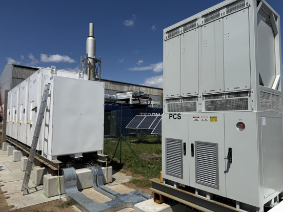
RMS models remain widely used for system-level and conventional stability studies, while electromagnetic transient (EMT) models are increasingly requested where converter interactions, weak-grid conditions or grid-forming behaviour require higher-fidelity assessment.
EMT studies can be particularly valuable when assessing:
- converter-driven oscillations;
- low-SCR interactions;
- current limiting;
- fault behaviour;
- black start;
- islanding and resynchronisation
- interactions between multiple inverter-based resources.
However, simply having an EMT model is not enough. The critical question is whether the model reproduces the behaviour of the actual PCS and the firmware that will operate onsite. That includes, where relevant:
- virtual inertia and damping parameters;
- current-limit logic;
- active/reactive power priority;
- voltage and frequency control;
- fault response;
- protection behaviour; and
- transitions between operating modes.
A model that produces excellent simulation results but does not accurately represent the equipment and firmware deployed onsite has limited engineering value. For this reason, model validation should not be treated as an isolated step.
A stronger validation chain is:
Grid requirements → Simulation → Controller validation → Factory testing → Site testing
Each stage should confirm, or where necessary refine, the assumptions made in the previous one. This traceability becomes particularly important when firmware, control parameters or plant-level configurations change during project execution.
If the model represents one control strategy while the equipment onsite is running another, the connection study can quickly lose its value. For developers and EPCs, model-to-hardware consistency is therefore as important as model sophistication itself.
4. Grid-forming performance belongs to the plant, not just the PCS
Even the fastest and most sophisticated PCS does not operate alone. A utility-scale BESS is an interconnected system involving the battery, BMS, PCS, EMS, power plant controller (PPC), transformers, protection systems and the wider network.
Grid-forming performance, therefore, needs to be considered at the plant level. Take frequency response as an example. A PCS may technically be capable of changing active power extremely quickly, but whether the plant can actually deliver the requested response also depends on:
- battery SoC;
- available charging and discharging headroom;
- DC-side power and current limits;
- battery operating limits;
- thermal constraints; and
- the plant’s reserve strategy.
A PCS may be able to respond, but if the battery is operating close to its upper or lower SoC limit, the plant may not have sufficient headroom to sustain that response.
The same principle applies to islanded and microgrid operation. Asking simply, “How many PCS units can operate in parallel?” does not fully address the engineering challenge. Project teams may also need to evaluate:
- maximum and minimum load;
- sudden load steps;
- transformer energisation;
- motor starting;
- battery headroom;
- active and reactive power sharing;
- short-circuit capability;
- protection coordination;
- interaction between the PCS and plant-level controller.
This is particularly important in multi-PCS systems. Individual converters may perform correctly in isolation but behave differently when several units share a common bus, particularly if cable impedance, transformer characteristics, controller settings or communication delays differ across the plant.
A grid-forming PCS is therefore only one part of a grid-forming BESS. The final behaviour is determined by how the complete system works together.
5. Commissioning should prove what the models predicted
Ultimately, the site determines whether the engineering works. Commissioning should therefore do more than demonstrate that individual components can start, stop and follow basic commands. It should validate whether the behaviour assumed during grid studies and system design can actually be reproduced by the commissioned plant.
Depending on the project and local connection requirements, testing may cover:
- voltage and frequency control;
- active and reactive power response;
- load steps;
- operating-mode transitions;
- fault ride-through;
- black start;
- multi-PCS operation;
- PPC coordination;
- islanding and resynchronisation where applicable.
Where practical, measured responses should be compared with the behaviour predicted by the models. Significant deviations should trigger investigation into model parameters, firmware configuration, plant-level controls, communication or protection settings rather than being treated simply as a commissioning issue. This is particularly important because many integration problems do not become visible when individual components are tested independently.
A PCS may respond correctly, for example, while the PPC simultaneously sends a conflicting command. A protection setting that appears reasonable when considered independently may interrupt the intended grid-forming response. The battery may impose a power limitation that was not represented correctly in the plant controller. Or multiple PCS units that operate correctly individually may interact unexpectedly when operating together.
Experience across thousands of storage deployments shows why the final stages of integration deserve as much attention as the individual equipment. For EPCs, the objective should therefore be to close the gap between model, controller, equipment and site behaviour as early as possible.
From power electronics to project bankability
The grid-forming conversation is maturing. The industry is gradually moving away from asking: “Does this PCS support grid-forming?” towards asking:
“Has its behaviour been modelled, validated and demonstrated under the conditions my project will actually face?”
That is a much more useful question. For developers, EPCs and asset owners, these engineering details ultimately translate into commercial risk. A model mismatch, failed compliance test or late-stage control-system redesign can delay energisation and COD. Poor coordination between the PCS, battery, PPC and protection system can affect plant availability or prevent the asset from delivering the grid services assumed in its technical and commercial case.
Conversely, addressing these issues early can increase certainty throughout project execution. For developers, this can reduce grid -connection and commissioning risk. For EPCs, it can reduce late-stage redesign, repeated testing and integration work.
For asset owners and investors, it provides greater confidence that the BESS can achieve its intended availability and evolve beyond energy shifting to provide the dynamic services increasingly required by power systems with high shares of inverter-based generation.
This is why power electronics remains central to the grid-forming discussion. The PCS is where software control meets physical electrical limits. Converter topology, semiconductor capability, current margin, thermal design and protection philosophy all influence how much of a sophisticated control strategy can ultimately be delivered to the grid.
For developers, EPCs and asset owners, the real measure of grid-forming capability is therefore not whether it appears on a datasheet, but whether it survives the full journey from grid code and simulation to commissioning and commercial operation. The future of grid-forming will not be defined by a single algorithm. It will be defined by how effectively power electronics, control systems, grid models and project engineering work together.
About the Author
Luke Lu is technical director at SINEXCEL, with extensive experience in power electronics, energy storage PCS and grid-forming technologies. He has been involved in the development and application of utility-scale energy storage solutions, with a particular focus on grid-code compliance, converter control, weak-grid operation and project commissioning. At SINEXCEL, he supports the development and deployment of PCS solutions across global energy storage projects.