Ensuring battery systems used in conjunction with solar perform safely and optimally is essential in the continued roll-out of storage technology. Robert Puto and Gerhard Klein of TÜV SÜD examine independent technical assessments that must be undertaken before a storage system is built.
This article first appeared in ‘Storage & Smart Power’, Energy-Storage.news’ dedicated section of the quarterly technical journal PV Tech Power. Volume 22, in which it appeared, was first published online in mid-February.
Enjoy 12 months of exclusive analysis
- Regular insight and analysis of the industry’s biggest developments
- In-depth interviews with the industry’s leading figures
- Annual digital subscription to the PV Tech Power journal
- Discounts on Solar Media’s portfolio of events, in-person and virtual
It is obvious that the purpose of generating solar energy is essentially its transformation into useable electric power. Because of its fluctuating nature, the timing and the magnitude of this generation cannot be controlled, nor can it be managed in correspondence to high or low demand from consumers.
The rise of solar and wind (and the concurrent decline of fossil fuel) generation demands a stable integration into existing power grids. In addition, smart grids offer the flexibility to store energy during periods of surplus and low demand/low price, and consume it during peak-demand/high price. The solution is energy storage.
On the one hand, this solution must be efficient and fast enough to prevent grid instability; on the other, it must operate safely for users and without causing negative impact on the environment. These are necessary conditions for public acceptance.
In technical terms, storage systems should have the following properties:
- So-called “four quadrant operation”, i.e. full operation for all combinations of active and reactive power.
- Renewable firming, i.e. provision of backup power to tighten the output of a PV system and ensure a continuous power supply.
- Reactive power control to establish reactive power supply to meet any grid requirements.
- Peak-shaving and -shifting in power production to shave, store and deliver energy when needed.
- Ramp rate control to buffer output changes of intermittent renewable energy sources.
- Active power management as frequency-dependent control to support the grid.
- Fault ride through (FRT) properties, i.e. the capability of staying connected during short network voltage dips, must comply with local requirements.
On 19 August 2019, a lightning strike triggered a series of events that led to the disruption of the UK’s power grid resulting in power loss for one million consumers for up to 45 minutes and 1GW of disconnected electricity demand. This is a clear example of how critical it is to design a well-balanced and stable grid, where generators, protective devices, suitable backup power (from energy storage systems), power management systems, etc., provide enough inertia to prevent critical voltage and frequency instability.
Beyond the societal and ecological aspects, renewable energy combined with energy storage must also prove economically viable, i.e. competitive when compared to fossil, or nuclear power generation.
TÜV SÜD offers a holistic approach, consisting of combined top-down and bottom-up analyses for a most comprehensive ESS assessment. Top-down analysis come from system-level considerations, whereas bottom-up from component level. In this article we present our approach to utility-scale PV plants combined with electrochemical battery storage solutions, as one of the most interesting applications.
Technical due diligence (TDD)
Generally, investment projects require a due diligence (DD) process based on a thorough assessment of legal (LDD), financial (FDD) and commercial aspects (CDD). It has evolved to become a quasi-standard for project financing and financial transactions. In the case of projects driven by new technology, it is necessary to have a sound evaluation of technical feasibility, opportunities and risks associated with the technological solution proposed.
Third parties are engaged in technical due diligence (TDD) activities to identify critical issues or risks, and for technical advisory concerning possible mitigation measures. It is important to note that such a technical due diligence is not only an engineering exercise. It also takes into consideration the interactions between different project stakeholders shown in Figure 1.
In other words, technical evaluations during the TDD assessment are relevant to LDD, FDD and CDD work streams.
Below is a description of the main activities performed under top-down and bottom-up technical due diligence.

Top-down TDD activities
Amongst various system-level assessments made, particular attention shall be paid to:
System design and profitability
Although different designs are possible from a technical point of view, the benefit/cost ratio may depend on other factors as well. In [1], different connections to the grid of a PV plant plus storage systems have been considered for a system model located in California (independent PV and storage system, AC-coupled PV plus storage system, DC-coupled system with flexible charging and DC-tightly-coupled with PV-only charging). Depending on whether there is an investment tax credit (ITC), either the “DC-coupled system with flexible charging”, or the “DC-tightly-coupled with PV-only charging” will result being the “best solutions” from a benefit/cost perspective.
Figure 2 shows how sensitive the benefit/cost is ratio to factors such as system location and support policies in place, on top of design-related factors, such as AC-coupled versus DC-coupled PV + storage models.

Criteria for battery technology
Careful criteria for the selection of a suitable battery type for the storage shall be defined during the early feasibility stage. Lithium-ion (Li-ion) batteries are currently widely used in stationary utility-scale storage applications, with several technologies available [2]. It’s important to note that the combination of different types of electrolytes with different electrode materials can result in very different battery characteristics. Therefore, the first selection criterion is based on the assessment of the maturity of the technology.
The next selection criterion we use is based on safety considerations. Given the high energy levels involved (currently between 200Wh/l to 350Wh/l, in uptrend towards 250Wh/l to 550Wh/l by 2030) in combination with highly flammable nature electrolytes, intensive R&D is ongoing focused on optimisation of different layouts and cell designs. One of the “worst case scenarios” that needs to be prevented is the so-called “thermal runaway”.This might be the consequence of external events causing overloading of cells thus overheating, or even worse, short circuits in the cell structure which can trigger uncontrollably high temperature rises leading to hazards like burning, fire and explosion of the cells. Deep discharge is another phenomenon that should be controlled as it may cause corrosion.
Cost is obviously a very important factor to be considered for Li-ion systems. Its current learning curve is on a steep decline, which is a very good news. According to BNEF’s Long-Term Energy Storage Outlook, the capital cost of a utility-scale lithium-ion battery storage system is expected to decrease by around 52% between 2018 and 2030 [3].
Another significant development we will witness in the short to medium term is the application of second-life batteries. This will further accelerate the downward trend of Li-Ion battery price. In fact, according to recent studies, second-life battery supply from used EV batteries of electric vehicles could exceed 200 GW-hours per year by 2030 for stationary applications, which might even exceed the demand for Lithium-Ion utility-scale storage for low- and high-cycle applications combined [4]. However, due to different designs of EV-battery packs, fragmentation of volume in the automotive sector and a gap in standardisation addressing second-life batteries, there is no guarantee today regarding their quality and performance. Furthermore, nascent but immature regulations might create uncertainties for OEMs, second-life battery companies, and potential users. Technical developments are underway on second-life battery safety standards, involving all industry stakeholders. The final goal is twofold: on the one hand, creating transparency into product supply and market demand [4], on the other, matching battery performance potential with storage application requirements through a classification method for both.
Criteria for battery management system (BMS)
The battery management system (BMS) is essential to the safety and performance of the entire ESS system: it has a controlling and monitoring function, hence its specifications and functions need to be checked, tested and validated.
Controlling and monitoring the state of charge (SoC) of the battery cell through its parameters (current, voltage, temperature) during charging and discharging is a critical function based on which functional safety for fault protection is designed.
In addition, BMS does fault recording and connection/disconnection of the battery system, and acts as a balancing function by optimising the usable system capacity. These functions are necessary because of differences in cell capacity and internal resistance due to manufacturing methods and modes of use. When the cells are connected, they will charge and discharge differently, which in turn can lead to deep discharge or overcharging of cells. Cell balancing allows for usable capacity to be maximised, and at the same time for an increased service life. The state of health (SoH) defines the residual capacity at a given time and is used for the characterisation of the remaining usable capacity.
Finally, the BMS has the function of controlling thermal management, as the efficiency and ageing of the cells are highly dependent on temperature. Increased temperatures lead to more rapid degradation of the materials and faster ageing of the battery, while lower temperatures impede the flow of current as the conductivity of the electrolyte is reduced. In order to ensure normal operation, optimum power output and service life, the system will require cooling at high temperatures and heating in cold weather.

Bottom-up TDD activities
For a comprehensive, overall validation, also component-level requirements shall be met. Hereby we would like to highlight the importance of the following:
Battery testing Safety, performance, reliability and environmental tests are conducted in the laboratory. Test methods are in accordance with international and local battery standards as listed in Table 1.
Above all, we would like to highlight the importance of the following three standards:
1) IEC 62619 – Safety requirements for secondary lithium cells and batteries, for use in industrial applications; 2) UN 38.3- Battery Transport Requirements; 3) IEC 62620 – Performance requirements for secondary lithium cells and batteries, for use in industrial applications. (Worth noting, too, are the country-specific regulations: VDE-Germany, UL-USA, JIS-Japan, KBIA-South Korea, GB-China.)
| IEC 62619:2017 | Secondary cells and batteries containing alkaline or other non-acid electrolytes – Safety requirements for secondary lithium cells and batteries, for use in industrial applications | Safety testing |
|---|---|---|
| IEC 62620:2014 | Secondary cells and batteries containing alkaline or other non-acid electrolytes – Performance requirements for secondary lithium cells and batteries, for use in industrial applications | Performance testing |
| IEC 61427-1:2013 | General Requirements and Test Methods for Renewable Energy Storage Batteries and Battery Units. Part 1: Photovoltaic Off-grid Applications | Performance, lifecycle testing |
| IEC 61427-2:2015 | General Requirements and Test Methods for Renewable Energy Storage Batteries and Battery Units. Part 2: Grid Connection Applications | Performance and lifecycle testing |
| VDE-AR-E 2510-50:2017 | Stationary battery energy storage systems with lithium batteries – Safety requirements | Safety, reliability, environmental |
| UL 1973:2018 | Batteries for Use in Stationary, Vehicle Auxiliary Power and Light Electric Rail (LER) Applications | Safety, environmental, reliability testing |
| JIS 8715-1:2019 | Secondary Lithium cells and batteries for use in industrial applications- Part 1 : Tests and requirements of performance | Performance testing |
| JIS 8715-2:2019, J62619 | Secondary Lithium cells and batteries for use in industrial applications- Part 2 : Tests and requirements of safety | Safety testing |
| KBIA-10104-03-7312 (2018), KC62619, KC 62620 | Secondary lithium-ion battery system for battery energy storage systems — performance and safety requirements | Safety, Performance testing |
| GB/T 36276-2018 | Lithium-ion Battery for electrical energy storage | Safety, lifecycle, reliability testing |
| UN 38.3 (Ver.6 + A1) | Battery Transport Requirements (UN Handbook, Recommendations, Tests and Standards for the Transport of Dangerous Goods) | Environmental, reliability testing |
Examples of test failures
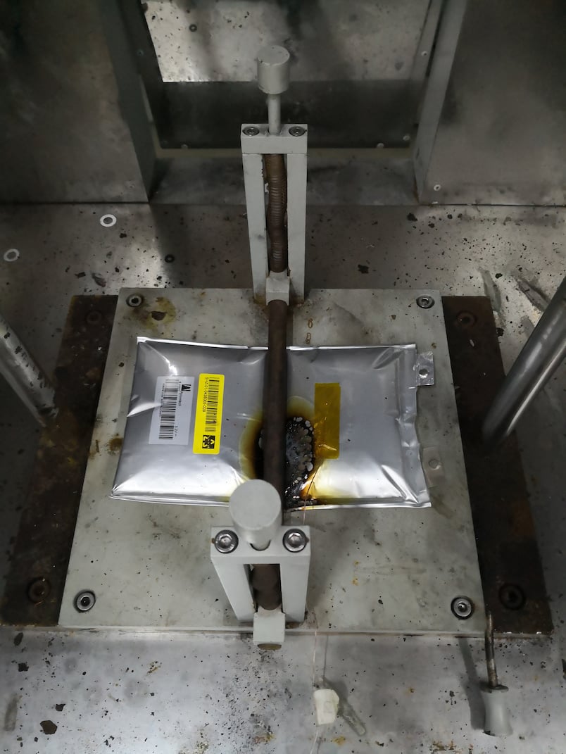
Impact test. Is defined in clause 7.2.2 of IEC 62619 – Safety requirements for secondary lithium cells and batteries, for use in industrial applications. Figure 4 shows the effect of the failure of the battery under the specified test conditions. The overheating phenomenon, called “thermal runaway”, is triggered within the battery cell structure. The sequence of cause-effect events leading to fire starts with mechanical pressure applied on the battery, finally leading to fire (mechanical pressure => damaged cell structure => internal short-circuit =>overheating => fire). The root-cause for the failure is the solidity of the separator between the two electrolytes inside the battery. The separator, if too thin, or made of inadequate material, may get punctured under the applied crushing pressure, hence giving rise to an internal short circuit, and consequently to uncontrollable overheating and burning. Although the impact test does not feature among those with the highest failure rates in laboratory testing, it is very important to execute it correctly given the disruptive risk associated with it. In the test, a cell (or cell block) is first discharged at a constant current of 0.2It A to 50% SOC. A stainless steel bar is placed across the centre of cell, thus 9.1kg rigid mass is dropped on the sample from a height of 0.6m. The acceptance criterion is that the impact shall not cause fire or explosion.
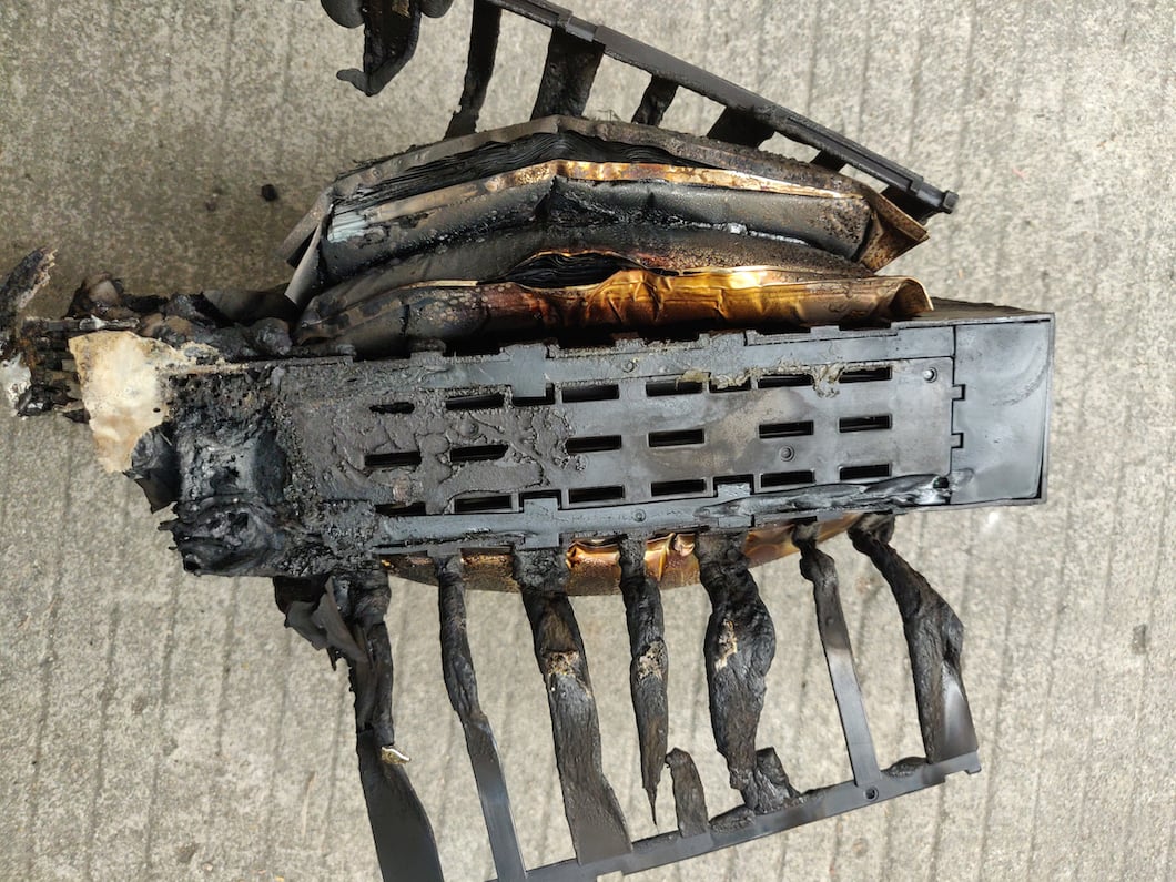
External short-circuit test. Is defined in clause 38.3.4. of UN 38.3 – Battery Transport Requirements. It can result in a “thermal runaway” inside modules of cells without adequate protection. Normally modules are equipped with an internal protective device called CID (current interruption device) designed to intervene during the short-circuit test. If this doesn’t happen reliably, burning can occur (Figure 5), and thus the failure of the test. Redundancy in protection levels might be necessary.
Functional safety. Failure of the control system is more frequently encountered during the following safety tests of the above mentioned IEC 62619:
1) clause 8.2.2 Overcharge control of voltage (battery system); 2) clause 8.2.3 Overcharge control of current (battery system); 3) clause 8.2.4 Overheating control (battery system).
Performance tests. Covered by IEC 62620 – Performance requirements for secondary lithium cells and batteries, for use in industrial applications. Attention shall be paid to endurance tests according to: 1) clause 6.6.1 Endurance in cycles and 2) clause 6.6.2 Endurance in storage at constant voltage (permanent charge life).
Risk assessment and validation for PCS, BMS and EMS
Power conversion system (PCS), battery management system (BMS) and energy management system (EMS) are the main pillars on which the entire system, its controls and protections rely. Our guiding principle for a final judgement is a thorough risk assessment of the three pillars mentioned above. It starts with hazard identification, continues with risk analysis and finally evaluates the measures implemented for risk reduction. The following standards are applied throughout the risk assessment:
IEC TS 62933-5-1: 2017 – Electrical Energy Storage, Safety considerations for grid-connected EES systems. Is used to classify hazards in eight categories: electrical, mechanical, explosion, fire, temperature, chemical, exposure to electric/magnetic/electromagnetic fields, and unsuitable working conditions. Different technologies present different hazards. Clause 7 of this standard provides detailed guidance on risk assessment procedures, risk reduction measures and damage propagation for grid-connected applications.
IEC TS 62933-4-1: 2017 – Electrical Energy Storage, Guidance on environmental issues. Provides guidance to environmental reliability. ESS shall be capable of withstanding severe environmental conditions per its intended use, under conditions such as water, dust, humidity, salt mist, exposure to solar irradiation of enclosures, low/high temperatures, seismic vibrations.
IEC 62933-2-1: 2017 – Electrical Energy Storage, Unit parameters and test methods. Provides methods for checking main system parameters per intended use, such as nominal energy capacity, input/output power ratings, roundtrip efficiency, expected service life, system response, self-discharge, etc. In addition, performance parameters related to grid compliance, such as duty-cycle round-trip efficiency, fluctuation reduction, black start output voltage, grid connection compatibility, etc, shall also be tested.
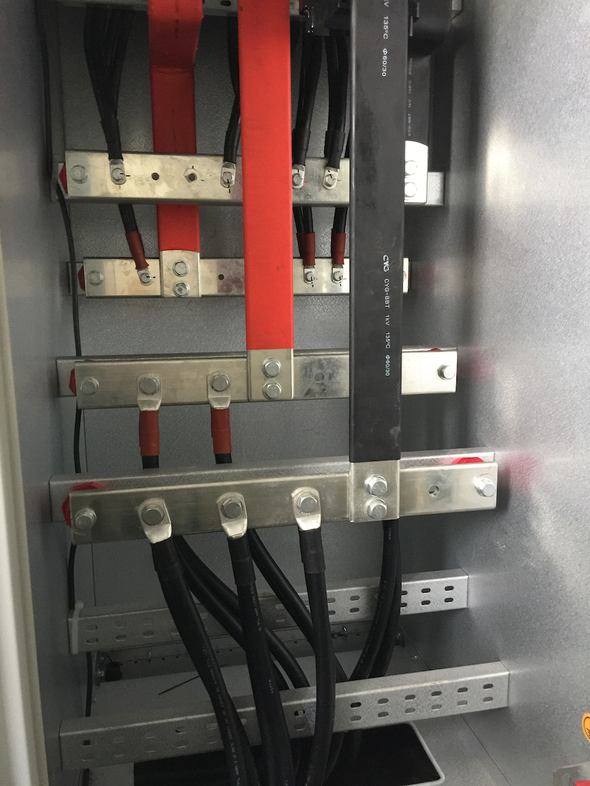
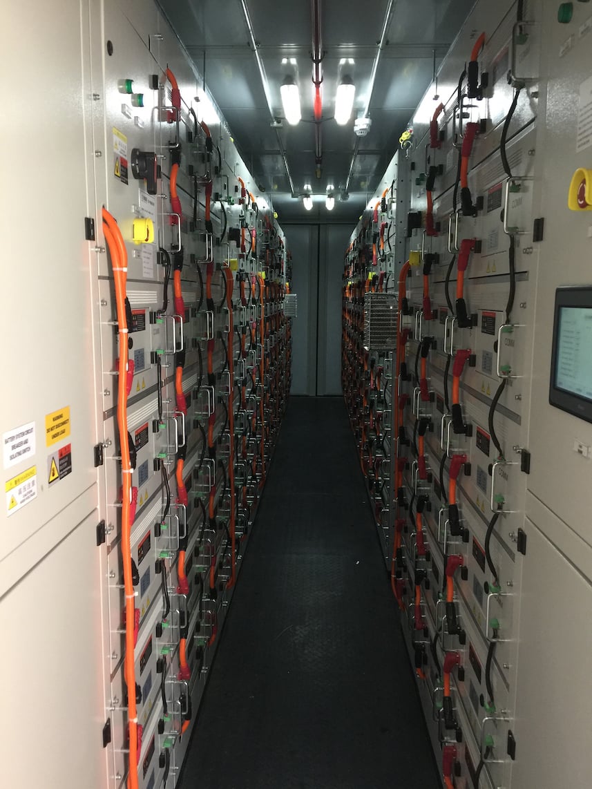
Dedicated programme for utility-scale, containerised ESS systems
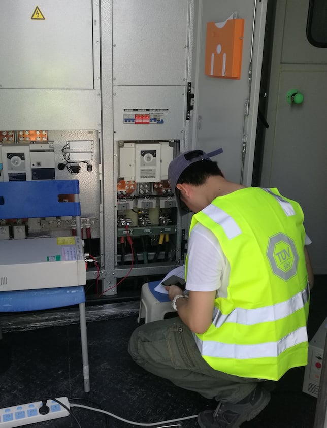
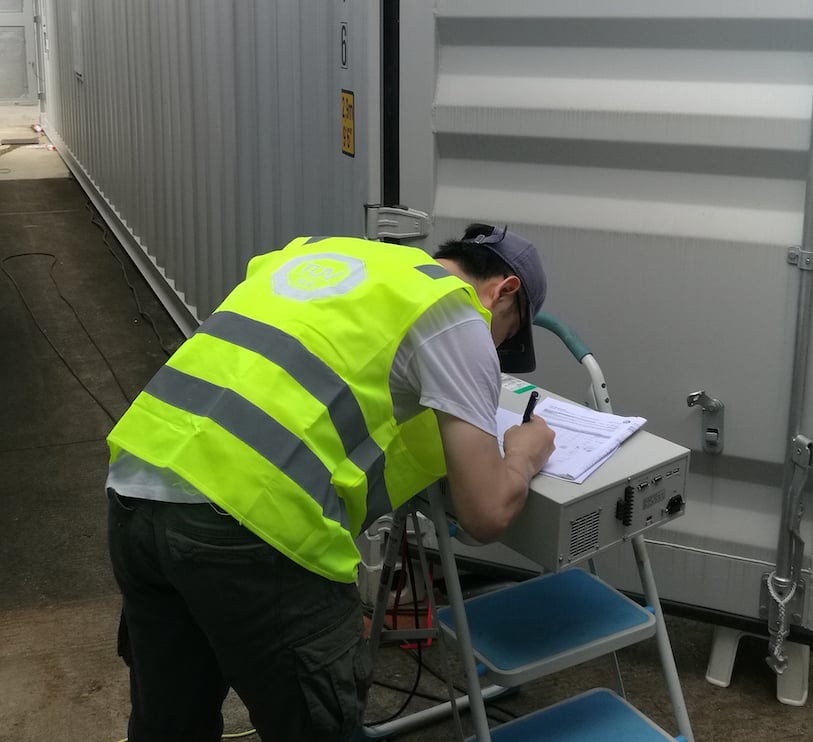
TÜV SÜD PPP 59044A is a verification, testing and validation procedure for utility-scale, containerised battery storage systems. It is performed after the battery testing and is mainly based on the above mentioned standards (IEC 62933-5-1, -4-1, -2-1). It consists of three activities, two of which conducted on-site:
- Documentation review: System diagrams, BMS, PCS, ESS, container, lighting, air-conditioning & ventilation, fire protection systems, etc.
- Construction checks (on-site): Coinsistency of materials/parts (BOM), fixing methods/installation of components/parts, functional checks of all sub-systems, wiring system, fire-protection system, isolation/overcurrent protection devices, protection against electric shock, etc.
- Safety tests (on-site): Insulation resistance, voltage test, earth continuity, verification of protection by automatic disconnection of supply, ingress protection (IP rating), door fan integrity, noise level, etc.
Particular attention shall be paid to the insulation system coordination between all parts of the ESS system in order to prevent total breakdown. It is therefore essential that it is inspected and tested during the project. In case of systems with multiple PV power sources, the insulation stress caused by the system voltage, working voltage, temporary and impulse overvoltage on the other circuits and components connected to the PV sources shall be tested. For example, for a PV source rated 1,000 VDC with overvoltage category II, all circuits connected shall withstand a working voltage test on the insulation between the PV source and earth of 1,600 VDC (1 min) and 4,464 Vpeak impulse test.
Additional TDD activities
Beyond the engineering judgement, we are also involved in the assessment of contracts, permits and licences (related to legal due diligence).
Contracts are the basics of a project. As far as they include technical specifications, the following aspects shall be assessed from a technical perspective. This holds especially true for EPC and O&M contracts:
- Is the scope of supply and services defined sufficiently?
- Are prices and pay-out mechanisms according to industry standards?
- Have arrangements regarding amendments been made in a transparent way?
- Have periods of performance/supply been defined reasonably (e.g. hand-over conditions)?
- Are the provisions on warranties and guarantees as expected (liability, performance guarantee for battery cells)?
- Do the provisions on penalties cover the project needs?
- Are all permits, certifications and qualifications available or can we expect they will be available in time (considering the experience of the project partners involved)?
- Are there remarkable political or country risks (higher level of security measures required?)
Considering Li-ion cells, e.g., major ethical concerns were raised in different countries with respect to quarrying cobalt or lithium under conditions of child labor or forced labor. This issue might lead to a more restrictive legislation or even prohibition on the use of such materials.
Market expectations (related to commercial due diligence)
The market development determines the revenue streams, but also possible competitive technologies coming up during the lifetime of the project must be considered:
- What is the main source of revenue? (feed-in tariffs? Renewable Portfolio Standards? Capacity charge or working price?)
- What is the off-take and sales risk?
- How has it developed in the past? What are expectations for the future?
- Will the project be able to master future challenges?
Investor expectations (related to financial due diligence)
In order to fully capture the economic opportunities of combined PV-energy generation and ESS on the one hand, and on the other mitigating the risk of failing to generate adequate income, a thorough evaluation of the financial planning is needed also from a technical perspective:
- Are LCOE and IRR realistic?
- Are CAPEX and refurbishment expenditures planned reasonably?
- What is included in OPEX and are the assumptions well-founded?
- Finally, is the business plan (revenues and expenditures) realistic?
Final considerations
Applying system-level technical due diligence from an early design phase is key to building a solid business case. Applying component-level technical due diligence during project implementation is key to securing efficient operations and therefore the expected financial returns. Ignoring or overlooking the safety aspects, or lack of expertise in risk assessment activities, can lead to very harmful consequences from a legal, financial and commercial perspective.
Clear examples of the type and scale of damages incurred are the fire accidents in South Korea from August 2017 involving 23 lithium-Ion ESS systems and resulting in the shutdown of 533 ESS units with US$32 million losses. The investigation committee formed by the Ministry of Industry identified four root causes: insufficient battery protection systems against electric shock; inadequate management of operating environment; faulty installations due to faulty wirings and damage to batteries; and deficiencies in ESS integration. In particular, deficiencies regarding the battery management system (BMS), energy management system (EMS), and power management system (PMS) were the root causes which led to fire.
References
[1] NREL, 2017, Denholm, P., Eichman, J., Margolis, R., Evaluating the Technical and Economic Performance of PV Plus Storage Power Plants, NREL (National Renewable Energy Laboratory) Technical Report NREL/TP-6A20-68737, August 2017
[2] IRENA, 2017, Electricity Storage and Renewables: Costs and Markets to 2030, International Renewable Energy Agency, Abu Dhabi.
[3] BloombergNEF, https://about.bnef.com/ blog/behind-scenes-take-lithium-ion-battery-prices/, download 07.12.2019; https://about.bnef.com/blog/energy-storage-620-billion-investment-opportunity-2040/, download 07.12.2019
[4] McKinsey (2019): Engel, H., Hertzke, P., Siccardo, G., “Second-life EV batteries: The newest value pool in energy storage”, McKinsey Center for Future Mobility, April 2019 (https://www. mckinsey.com/industries/automotive-and-assembly/our-insights/second-life-ev-batteries-the-newest-value-pool-in-energy-storage, download 16.12.2019)
All images: TÜV SÜD except where stated.
This article first appeared in ‘Storage & Smart Power’, Energy-Storage.news’ dedicated section of the quarterly technical journal PV Tech Power. Volume 22, in which it appeared, was first published online in mid-February. Download the entire 104-page journal as a PDF, free of charge, here. Alternatively, you can download this paper as a standalone PDF from the ‘Resources’ section of this site.
