

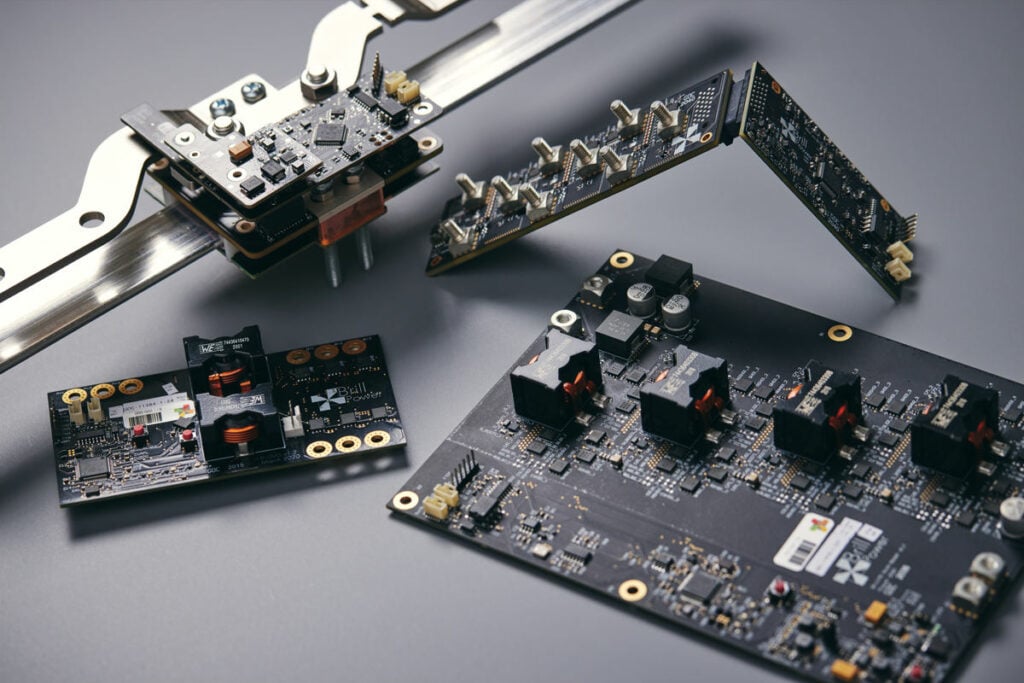
Battery energy storage systems are placed in increasingly demanding market conditions, providing a wide range of applications. Christoph Birkl, Damien Frost and Adrien Bizeray of Brill Power discuss how to build a battery management system (BMS) that ensures long lifetimes, versatility and availability.
This is an extract of an article which appeared in Vol.29 of PV Tech Power, Solar Media’s quarterly technical journal for the downstream solar industry. Every edition includes ‘Storage & Smart Power,’ a dedicated section contributed by the team at Energy-Storage.news.
Every modern battery needs a battery management system (BMS), which is a combination of electronics and software, and acts as the brain of the battery. This article focuses on BMS technology for stationary energy storage systems. The most basic functionalities of the BMS are to make sure that battery cells remain balanced and safe, and important information, such as available energy, is passed on to the user or connected systems.
Balancing is needed because battery systems are made up of hundreds, sometimes thousands of individual cells, which all have slightly different capacities and resistances. These differences increase over time as the cells degrade at different rates. If the cells are not balanced at least occasionally, their voltages will soon drift apart to an extent that the battery capacity becomes unusable.
Try Premium for just $1
- Full premium access for the first month at only $1
- Converts to an annual rate after 30 days unless cancelled
- Cancel anytime during the trial period
Premium Benefits
- Expert industry analysis and interviews
- Digital access to PV Tech Power journal
- Exclusive event discounts
Or get the full Premium subscription right away
Or continue reading this article for free
Safety is ensured by keeping the cells within safe operating limits of voltage, current and temperature, which is particularly important for lithium-ion batteries. If cells get over-charged, charged at very low temperatures, or exposed to excessive currents or temperatures, they could develop faults that may lead to fires or explosions.
Information such as available energy and power cannot be directly measured, which means the BMS must compute
it based on measurements of voltage, current and temperature. These computations are called state estimation and the results are passed on to higher-level systems, including user interfaces.
Before we look at BMS design considerations in more detail, it is worth describing the different types of BMS and industry requirements that inform design choices. The balancing approach is typically used to classify BMS types, although other design aspects play important roles, such as different approaches to state estimation and information flows.
Basic Pack Construction
Cells, or electrochemical cells, like lithium-ion cells are the smallest unit of energy storage within a pack. They come in various physical sizes which directly relate to their capacity. The minimum voltage of a Lithium-ion cell can be as low as 2.5V (for LFP cells) and the maximum voltage can be as high as 4.3V for NMC chemistries.
Cells are connected in parallel to increase the maximum current that can be drawn from the pack. A group of parallel connected cells are called a super cell.
In general, the cells within a super cell will self-balance and there is no need to manage them further. Exceptions can include novel chemistries like lithium sulfur and chemistries with flat state of charge versus voltage curves operated in extreme C-rate conditions like lithium iron phosphate.
Super cells are connected in series to form a string. A battery pack usually consists of a single string. Connecting super cells in series increases the voltage of the pack, which is necessary in high power applications to prevent otherwise extremely high operating currents.
When adding cells to a battery pack configuration, the energy capacity increases. Therefore, adding parallel cells to a super cell increases the pack’s energy capacity, as does connecting an additional super cell in series.
BMS types
Balancing approach
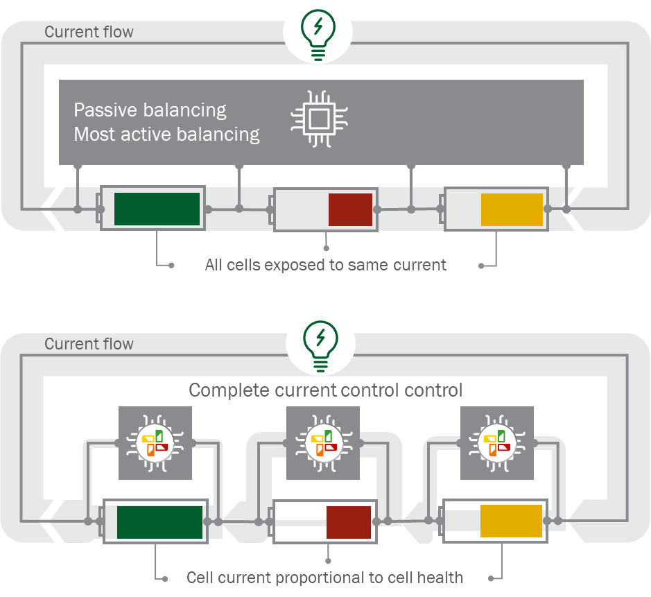
Passive balancing synchronises cell voltages at the end of the charge process by dissipating energy, which would have gone into fully charged cells, as heat via resistors. The advantage of this approach is the low component cost of the electronics.
Disadvantages include that all cells are exposed to the same current, which means that the weakest series-connected cells limit the energy, power, lifetime and safety of the whole battery. Cell degradation is accelerated since the current on weaker cells is higher relative to their capacity, which can also cause localised hot spots that may lead to de-rating of battery power or even safety issues. Moreover, energy is wasted during the charging process. The passive BMS can only monitor the pack current and interrupt it via a disconnect switch in the event of a fault.
If bi-directional information flow is implemented, system-level parameters such as operational settings may be changed to prioritise either battery lifetime or performance. Lifetime is prioritised by reducing the operational window at the expense of available energy or power, while performance is prioritised by widening the operational window, at the expense of battery life.
Active balancing is typically implemented via low-current bypass circuits, which direct low charging currents to cells that are not yet charged, rather than dissipating the energy as heat. The main benefit of this approach is to improve charging efficiency, which may be important if the available charging energy must be utilised as efficiently as possible. For most applications, however, active balancing does not justify the added component cost for the benefits they yield. Like with passive balancing, cell degradation is accelerated by higher relative currents on weaker cells and hot spots may form.
Complete current control is a novel approach to battery control and management, recently developed and patented
by our team at Brill Power, a spin-out company of Oxford University. The current on each super cell (or small super cell string) is continuously regulated in proportion to the health of the cells – weaker cells are exposed to lower currents, stronger cells to higher currents. This ensures that all available energy and power is utilised, no single cell or cell group limits the lifetime of the battery, and degradation on weaker cells is slowed down.
Safety benefits of complete current control include avoiding the formation of hot-spots by reducing the currents on cells with high resistance, and cell-level disconnects to contain any possible faults. This approach also has the benefit of system-level voltage regulation, which enables the direct integration of the battery with DC power sources, such as solar PV, fuel cells and other battery types, as well as with DC loads, such as EV chargers. The component cost of this approach is higher than for a passive balancing BMS, when the BMS is viewed in isolation, but lower when viewed at a system level.
The lower system cost is achieved by reducing battery size for a given performance and avoiding additional hardware such as DC/DC converters or inverters (which are needed to link solar PV and storage, or storage and EV charging). Total cost of ownership is reduced by extending battery lifetime by up to 60%, according to analyses by Brill Power and WSP.
Other, niche approaches to BMS technology include cascading cell bypasses and the integration of inverters, but we will not discuss them further here due to their limited applicability.
State estimation
Estimation of the State of Charge (SoC) and State of Health (SoH) is based on a combination of battery models and estimation algorithms. The level of sophistication and accuracy that is possible for state estimation and underlying battery models strongly depends on the hardware, which we use here to differentiate different approaches.
Integrated circuits (IC) are used in most conventional BMSs for state estimation, which are often referred to as ‘fuel gauge’. ICs are ‘hardwired’ with chemistry-specific battery models and state estimation algorithms. The advantage of ICs is that they are low cost. The disadvantages include limited system design flexibility and accuracy. The latter tends to get worse over time. Design flexibility is limited because ICs are typically created for a particular battery chemistry with particular specifications.
If the battery chemistry or specifications change, the IC also needs to be changed and the design adapted. The reasons for the limited and deteriorating accuracy are (i) state estimation on ICs is based on generalised representations of the battery chemistry and doesn’t capture the nuanced thermodynamic and dynamic properties of cells, which can vary between manufacturers, formats and batches, even for the same chemistry (ii) limited computing power on ICs constrains the complexity and fidelity of state estimation algorithms and underlying battery models, and (iii) cell characteristics change over time, which cannot be captured by hardwired IC algorithms, leading to increasing inaccuracy over time.
Microprocessors can be programmed with more complex, higher-fidelity battery models and state estimation algorithms, which can be fine-tuned to account for particular cell characteristics and specifications. The changing cell characteristics can be accommodated by updating the parameters of the state estimation algorithms and battery models, which keeps outputs more accurate over time. The same hardware can be used for any type of battery chemistry or manufacturer, allowing for ultimate design flexibility. The disadvantage can be higher component cost, depending on the required functionality and computational power.
Information flow
Uni-directional information flow is common in most battery systems: information flows from the BMS to higher-level systems and user interfaces. If the BMS is provided by the cell maker, less low-level information tends to be available, as this information can be considered sensitive. The most important information is safety and performance related and includes metrics such as SoC and SoH.
Bi-directional information flow is possible if the BMS can process inputs, such as changes to operational settings (for example maximal and minimal allowable cell voltage or SoC), or even updates to battery models or state estimation algorithms to maintain their accuracy, if microcontrollers are used.
BMS design and development
Once the appropriate BMS type has been identified, design and development can begin. The single most important factor in BMS design is the team and its expertise.
Traditionally, BMS design has been the domain of electrical engineers, who are indeed best placed to design the circuitry, but don’t typically have much knowledge of the inner workings of batteries. Designing the perfect BMS requires knowledge and expertise in electrochemistry, physics, electrical and electronic engineering, firmware development and data science.
With the right team in place, the first considerations should go to compliance with regulation and industry standards, since this has implications on both hardware and software design. Regulations and standards are typically specific to regions.
Although most regulation and standards apply to the battery system as a whole, some regulations apply to all electronic components and includes hazardous substance regulation, such as the RoHS and REACH directives in Europe. Relevant industry standards strongly depend on application and system specifications. Typical differentiators are residential vs industrial energy storage, and low vs high voltage.
The most relevant standards for industrial storage include IEC62619, UL1973, UL9549 and VDE-AR-E 2510-50. Product and functional safety are the most important aspect of these standards. Although the BMS is not required to be certified as a stand-alone component, it must not prevent the battery system from being certified. Testing and evaluation of prospective standard compliance by independent test and certification organisations, such as DNV, is therefore highly recommended.
This is an extract of an article from Volume 29 of PV Tech Power, our quarterly journal. You can buy individual issues digitally or in print, as well as subscribe to get every volume as soon as it comes out. PV Tech Power subscriptions are also included in some packages for our new PV Tech Premium service.
About the Authors
Christoph Birkl, DPhil, CEO and co-founder of Brill Power, has seven years’ experience in battery and fuel cell R&D and was recipient of the Royal Academy of Engineering’s SME Leaders Programme.
Damien Frost, DPhil, CTO and Co-founder of Brill Power, is a power electronics engineer with nine years’ experience developing products for high-tech start-ups.
Adrien Bizeray, DPhil, chief data scientist and co-founder of Brill Power, holds an MSc degree from Imperial College London and his PhD was funded by Samsung for the development of physics-based battery models.